A touchscreen is an input device that is normally layered on top of the display unit, e.g. computer monitor or cellphone screen, of an electronic system. One can give input or control the electronic system by touching with one or multiple fingers or through a special stylus. The touchscreen enables the user to interact directly with what is displayed or to control how it is displayed.
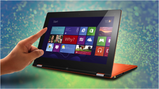 Figure 1, Touchscreen on a tablet computer.
The ever-increasing popularity of smartphones, tablets, and many other types of portable electronics drives the demand and acceptance of trouchscreen technologies. They are also found in many other fields, such as automated teller machines (ATMs), public kiosks, shopping mall displays etc., where rapid and intuitive interaction by the users with the display’s content is desirable.
A bit of history. The first touchscreen was developed by E.A Johnson at the Royal Radar Establishment, Malvern, UK in the late 1960s. Evidently, it was a capacitive type, which is the same as those widely used in smart phones nowadays. In 1971, Dr. Sam Hurst, an instructor at the University of Kentucky Research Foundation developped a touch sensor named ‘Elograph’. Later in 1974, Hurst in association with his company Elographics came up with the first real touchscreen featuring a transparent surface. In 1977, Elographics developed and patented a resistive touchscreen technology, one of the most popular touchscreen technologies in use today.
Types of Touchscreen Technology. There are four main touchscreen technologies: Resistive, Capacitive, Surface Acoustic Wave, Infrared.
1, Resistive Touchscreen Technology. A resistive touchscreen consists of a flexible top layer made of Polyethylene (PET) and a rigid bottom layer made of glass. Both the layers are coated with a transparent conducting compound called Indium Tin Oxide (ITO) and seperated by spacers, as shown in Figure 2. There are 4-wire, 5-wire, 7-wire, or 8-wire resistive touch screens, whith 4-wires being the most common type. As shown in Figure 2b, two of the wires are attached to opposite sides of the top conducting ITO layer (yellow outlines), while the other two are attached to the bottom ITO layer along the orthogonal direction.
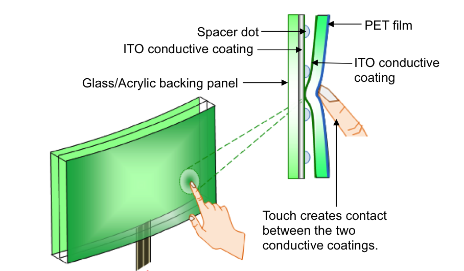
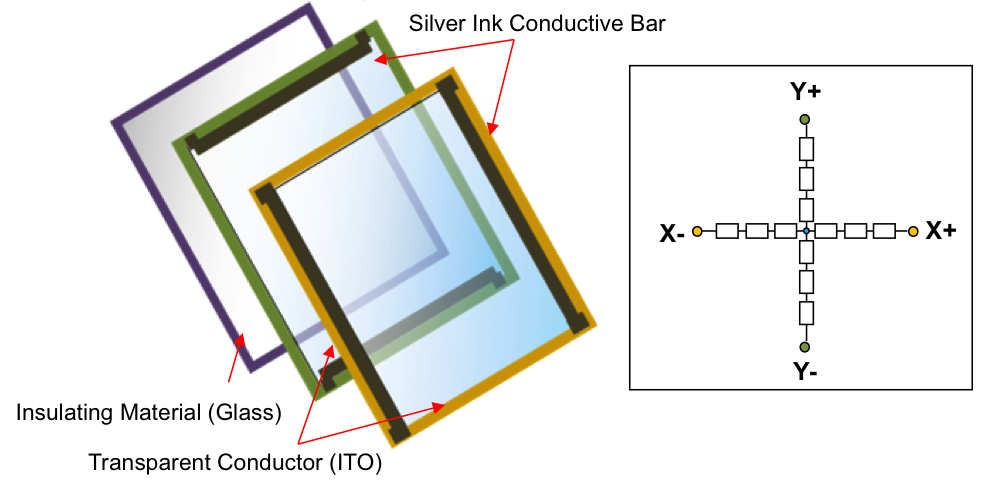 Figure 2. With the 4-wire touch screen panel, use the two active areas of the resistive touch screens to sense the X and Y pressure points (a). The equivalent circuit is simply a voltage-divider (b).
Upon touching, the flexable top layer depresses and connects to the bottom layer at the point of touching. The position of the touching point is determined as following: a voltage is applied between the two wires on one layer (e.g., X- and X+ silver ink conductive bars on top layer), the voltage will drop uniformaly from one wire to the other. At the point of touching, the whole bottom conducting layer takes the voltage of the touching point, which can be measured from the Y+ or Y- terminals (green). If the applied voltage is 2V and the touching point is half way between X- and X+, then a readout of 1V will be addressed. In principle, this voltage is proportional to the applied voltage between X+ and X- and the location of touching point along X direction. This measurement probes the X position of the stylus. The Y position is sensed when you apply voltage to opposing conductive bars on the Y layer and use the X+ or X- terminals to sense the Y position of the stylus.
Resistive touchscreens are cheap, easily available and consume low power. They well with almost any stylus-like objects and are widely used in ATMs, public kiosks etc. However, because of the constant bending of the top layer upon touching, resistive touchscreens are generally not very durable. For large-sized touchscreen, they tend to be less accurate and sensitive to environmental drift. Furthermore, these systems transmit only about 80% of light from the monitor.
Other types of resistive touchscreens have been developed over the years to address some of the issues. The Eight-wire Resistive Touchscreen is simply a variation of the 4-wire one with the addition of 4 sensing wires, two for each layer. The extra sensing points aid in reducing the environmental drift to increase the stability of the system. The 8-wire systems are employed in sizes of 10.4” or larger where the drift can be significant. The Five-wire Resistive Touchscreen has a different design than the 4-wire one. In this design, the coversheet has one wire connected to it and four wires are deployed to the four corners of the bottom sheet. The coversheet only acts as a voltage measuring probe. The functioning of the touchscreen remains unscathed even with changes in the uniformity of the conductive coating over the coversheet. The Six- and Seven-wire resistive touchscreens are also variants to the 5 and 4 wire technology, respectively. In the 6-wire resistive touchscreen an extra ground layer is added behind the glass plate which is said to improve system’s performance. While, the seven–wire variant has two sense lines on the bottom plate.